Getting Started Guide |
AVS/Express is an object-oriented, visual development tool that enables you to build reusable objects, application components, and sophisticated data visualization applications.
AVS/Express offers several ways to use objects. You can:
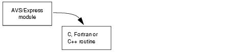
AVS/Express also provides full support for integrating C, Fortran, and C++ code. Components can perform their processing by calling a C, Fortran, or C++ routine. You can also use code template generators to import user-written code and data with little modification.
There are three aspects of AVS/Express that can be used to create a visualization application. You can use any combination of the main interface (the Network Editor), the AVS/Express V programming language and the V code processor (VCP), or you can use the AVS/Express application programmer interfaces (APIs).
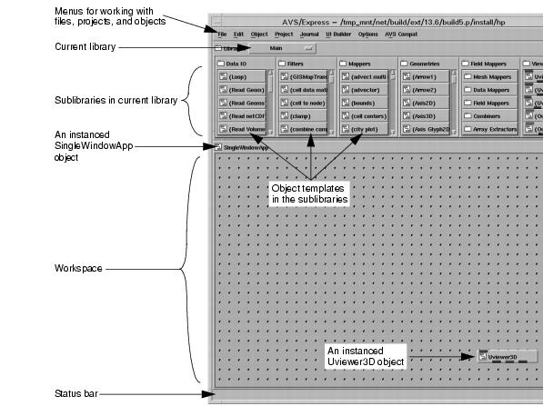
Your primary development tool is the Network Editor. The top section of the Network Editor consists of libraries of objects. The bottom section is the workspace where you drag and drop objects and draw connection lines between objects (connection lines indicate data references) to assemble an application or to create new objects.
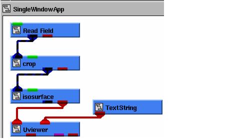
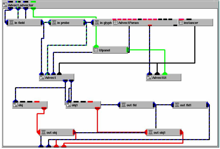
The graphic below demonstrates the simplicity of a complete data-visualization application as it appears in the application workspace.
By using only five objects (Read Field, crop, isosurface, Uviewer, TextString) and four connection lines, this application:
The Network Editor provides access to all AVS/Express objects, subobjects, and parameters; however, you can also view, add, delete, or edit objects by manually editing the underlying code for the objects. The code for AVS/Express objects is called V code.
You can access and use V code in several ways:
AVS/Express allows you to integrate user code into an application via application programmer interfaces (APIs). You can do this in two ways:
AVS/Express has several tools to help you integrate user code. For example, you can use AVS/Express' C++ class generator to generate a C++ class that controls an AVS/Express object.
Component technology is the ability to create an application from reusable, modular pieces, or components. AVS/Express offers component technology through its wide assortment of predefined application components. You can also use AVS/Express to create your own components or you can use components developed by other AVS/Express users.
AVS/Express organizes its predefined components into libraries. AVS/Express offers the following libraries:
AVS/Express supports many object-oriented techniques: the encapsulation of data and methods; inheritance; templates and instances; object hierarchies; derivation hierarchies, and polymorphism. Below is a very brief overview of how these techniques are used in AVS/Express. For a detailed explanation, refer to the Using AVS/Express.
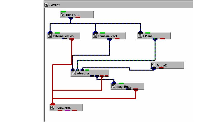
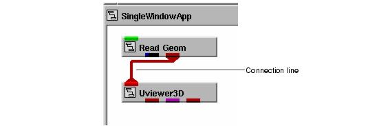
An AVS/Express object can reference another object's data. You do this by connecting the port of one object to a port of another object. For example, the application below shows a connection line between the red ports on the Read Geom object and the Uviewer3D object.
The Read Geom object reads a data file and creates an AVS/Express field and the Uviewer3D object provides a full-featured data viewer. The connection line between the two objects specifies that Uviewer3D should display the data created by Read Geom. Uviewer3D does not copy Read Geom's data; instead, it references the data.
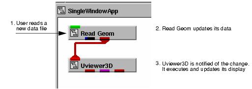
In AVS/Express, connections not only define how an object gets its data, the connections also drive the execution of the application. When data changes, objects that reference the data are notified of the change, and this typically causes the object to execute.
For example, consider the data visualization application consisting of Read Geom connected to Uviewer3D. If the developer of this application decides to read a new data file, the act of reading a new data file causes Read Geom's data to change. Because Uviewer3D is connected to Read Geom, it is notified of the change, and this notification causes Uviewer3D to execute and render the new data.
In AVS/Express, order of execution is not determined by a set of procedural instructions or message-passing schemes that you would otherwise need to code, instead it is controlled by the connections that you make among the application's objects.
When necessary, you can explicitly control execution. For example, in cases where order of execution is important but ambiguous, you can indicate object dependencies to control execution. You can also use a C, Fortran, or C++ routine to explicitly set notifications on objects to force their execution.
At the heart of AVS/Express is a powerful runtime engine called the Object Manager. You do not see it, but the Object Manager manages the definition and execution of your application.
In general, the AVS/Express Object Manager makes no assumptions about the data it manages. However, to provide the optimized set of visualization tools included in the Data Visualization Kit a set of visualization-specific data structures are defined. These structures are collectively known as a field.
To build an application using the facilities of the Data Visualization kit, it is important to understand the field data structure. One of your first tasks will be to decide how to represent your data using AVS/Express fields.
A field can consist of four main components:
A cell set contains a node connectivity list, which is a list of indices into a field's array of node coordinates that describes how to connect the nodes. The cell set's type determines the shapes that are generated when the nodes are connected. For example, consider a cell set that describes a series of triangles. The first three elements in the node connectivity list indicate the indices of the coordinates that define the first triangle in the cell set. The second three elements indicate the indices of the coordinates that define the second triangle, and so forth.
The grid and cells together make up a mesh.
Cell data is associated with the group of nodes that make up each cell. Cell data is optional, not all fields will have cell data. AVS/Express can use this data when rendering the surface of the grid, or to interpolate to the node data.
Node data and cell data make up the data.
The data components (node data and cell data) are optional and you do not always need to explicitly provide cells.
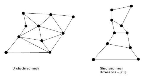
In AVS/Express, a mesh is formed by a grid and a cell. There are two basic types of meshes, structured and unstructured. Structured meshes have dimensions. The dimensions of a mesh are the number of nodes along each axis of the grid. Structured meshes have an implied connectivity. Unstructured meshes do not have dimension and require that you explicitly provide the connectivity.
The diagram below shows an unstructured and a structured mesh. Neither mesh looks particularly organized or structured, but there is an important distinction between the two. You can not specify the dimensions for an unstructured mesh; but you can specify the dimensions for a structured mesh.
|
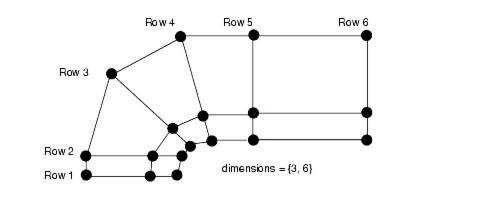
Below is a diagram of a structured mesh. The columns and rows form a 2 dimensional mesh. This diagram shows a structured mesh of dimensions 3x6.
|
Under the classification of structured mesh are two subclasses. These are Uniform and Rectilinear.
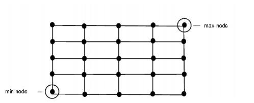
The uniform mesh is the most structured of the structured mesh types. In this type of mesh, the spacing of the nodes along each axis is uniform. The distance between two nodes along a given axis is the same. Because these is so much regularity in the spacing of the nodes in a uniform mesh AVS/Express can compute much of the grid information. You only need to specify only the coordinates of the minimum and the maximum nodes in a data set. Given those two nodes and the data set's dimensions, AVS/Express can compute the location of all other nodes. Below is an example of a 2 dimensional uniform mesh.
|
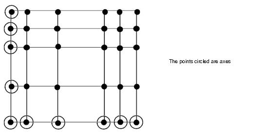
A rectilinear mesh is one where you specify only the nodes along the axes. The nodes need not be uniformly spaced. The location of all other non-axis nodes are computed by AVS/Express and are located at the intersection of the lines passing through the axis nodes. The mesh pictured below is a simple 2 dimensional rectilinear mesh.
|
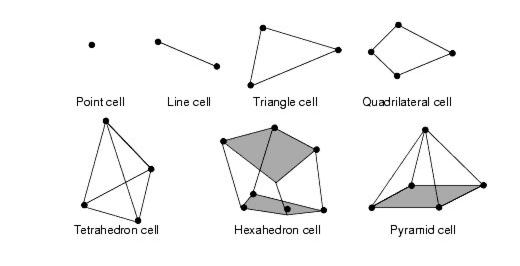
In an unstructured mesh you must explicitly define how the nodes are organized by using cell sets. Cell sets provide information on how the nodes and data are connected to each other. Each cell set needs to include the following information
|
When you work with AVS/Express, your goal is typically to create a data visualization application. The application could be for only your use, it could be something that will be used by other people in your company. What you deliver to the end user is an application. In AVS/Express terminology, what you work on while you are developing the application is called a project.
An AVS/Express project defines your development and execution environment. A project includes:
When you start AVS/Express, you access AVS/Express' development and execution environment, in other words, you start and access a default project. When you save your application, you save all of the objects that make up that application as well as the environment (libraries, code, and processes) that supports that application. In AVS/Express terminology, this means that you save a project for your application. The project that you save defines itself as being like the install project with any additions and changes you make.
Once you have created a project, you can define chains of projects, whereby a project is a derivative of some other project, which in turn is a derivative of yet another project. This allows a group of developers to share objects and work on specific objects that are unique to their own development tasks.
You can use AVS/Express in two ways to deliver complete applications as well as smaller application components.