(Feb 1, 2004 - many of the links in this document have gone stale over time. We are leaving the URIs present in the document for historical reference, but have not tried to update the URIs by searching for the original material.
Initial Visualization with Vtk
Overview
The ANAG AMR data with embedded boundaries was converted into flattened Vtk Structured Points (gridded data) and Vtk Poly Data (polygons). A Tcl/Tk program was then written (it was a heavily modified Vtk Tcl/Tk example) with took this data and allowed it to be visualized showing the embedded boundaries, grids, orthogonal slices, isosurfaces, and volume rendering. The ANAG AMR data and the embedded boundary information were in seperate files and were read by different components of the ANAG libraries so each was handled seperately.
The ANAG AMR data was read in and space for the highest resolution grid covering the entire problem size was allocated. Starting at the lowest resolution grid, the data for the selected quantity (e.g. "density") from all the FAB's at that level where written into the the allocated grid replicating the data as necessary. Thus, the finer data overwrote the coarser data but the coarser data filled in any places where there was no finer data. When this had been done for all levels the result was stored as Vtk Structured Points and written out.
The embedded boundary data was read and converted by modifying a program already written by ANAG, Ebis2Poly, to store the polygons as Vtk Poly Data and then writing that out.
At this point it was possible to read these two components into Vtk and visualize the results. This was done for density.
Sample Data Information
The data used in the following examples has a problem size of 64x64x32, with three levels of refinement:
- Level 0: 1 FAB, 16 x 16 x 8 cells.
- Level 1: 1 FAB, 32 x 32 x 16 cells.
- Level 2: 41 FAB's at various locations within the 64 x 64 x 32 problem size.
This was flattened into one 64 x 64 x 32 AVS uniform field and the embedded boundary information was converted in to 3688 polygons.
Vtk Visualizatons
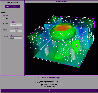
Full size GIF image (103K)
The image above shows an example of a visualization tool built using Vtk with its Tcl/Tk to visualize the flatten ANAG AMR data and the embedded boundaries. This example allows five different visualizations to be shown simultaneously: slices in each of the coordinate directions, the embedded boundaries, the AMR grids, an isosurface (of density), and a volume rendering (of density). In each case various parameters and options can be adjusted and the resulting visualization can be manipulated (e.g. rotated, scaled). This was quickly put together (1-2 days) to illustrate what might be possible using Vtk.
 Data slices
|
 Embedded Boundaries
|
 Outline of Grids
|
 Isosurface (density)
|
 Volume Rendering (density)
|
 All Grids
|
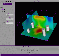
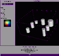
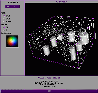
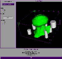
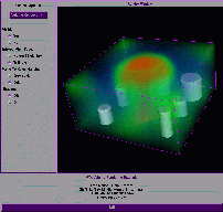
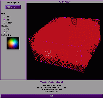
The images above illustrate individual portions of the visualization tool and show the control panel for each. Again, this is a simple example of what is possible and not a finished tool. It can be seen in the "All Grids" image that showing all the grids on all levels of refinement leads to an unsatisfactory result. Since the tool is written in a procedural language, Tcl/Tk, it is easy to modify and producing frames for animations is straightforward and most any parameter can vary from frame to frame.
Level of Detail |
Grids and Slices |
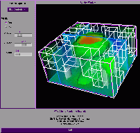
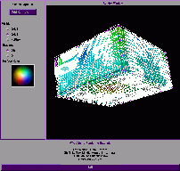
The left image above shows a feature built into Vtk which varies the level of detail in order to achieve interactive rendering. The image was taken while the scene was being rotated. During the rotation this lower level of detail image is produced and when the rotation stops a full resolution image is generated.
The right image above shows the result of moving the slice planes close to the edge of the data while all the grids are being shown. It is much easier to see what is going on close to the edge. Possibly using pairs of planes like this to clip the grids along with grid selection would make it easier to visualize grids.
Not shown here are the results of combining this data, Vtk, and two Vtk extension libraries which connect Vtk to the CAVE libraries. We found out about these extensions by posting message to the Vtk user group e-mail list asking about extension of Vtk to emmersive environments. One extension was from Futures Laboratory of the Mathematics and Computer Science Division at Argonne National Laboratory. Michael Papka contacted us about their efforts and made this code available to us to try with our data. The http://www.students.uiuc.edu/~mahall/vtkpage.html - other extension came from Matthew Hall who was working on http://bach.ncsa.uiuc.edu/PBS/ - a PBS project for NCSA. Both extensions allowed us to view the ANAG AMR data in our ImmersaDesk using the CAVE library. Due to problems in the calibration of our environment and the need to address the main visualization goals of this LDRD, this was not persued beyond this point.
Conclusions
Compared to AVS, Vtk provided a more flexible environment in which to visualize this data. Also, it comes with source code and there is a community which is actively extending its functionality, we can modify Vtk as necessary to fit our needs or use extensions made by other groups as they apply to our work. Vtk "out of the can" has no way to deal with hierarchies of collections of grids (e.g. ANAG AMR data). These explorations flattened the data as in the AVS explorations and suffers from all the problems this introduces. We were able to do a bit of simple grid visualization here. At least enough to know that we needed to do more!