Initial Visualization With AVS
Overview
The ANAG AMR data with embedded boundaries was converted into a flattened AVS uniform field and the list of polygons. Each of these was read into AVS and various visualizations (see below) were done with this data. The ANAG AMR data and the embedded boundary information were in seperate files and were read by different components of the ANAG libraries so each was handled seperately.
The ANAG AMR data was read in and space for the highest resolution grid covering the entire problem size was allocated. Starting at the lowest resolution grid, the data for the selected quantity (e.g. "density") from all the FAB's at that level where written into the the allocated grid replicating the data as necessary. Thus, the finer data overwrote the coarser data but the coarser data filled in any places where there was no finer data. When this had been done for all levels the result was stored as an AVS uniform field.
The embedded boundary data was read and converted by a program already written by ANAG, Ebis2Poly, and then the output was converted into the form needed by a example polygon reading program provided with AVS.
At this point it was possible to read these two components into AVS and visualize the results. This was done for both density (a scalar quantity) and momentum (a vector quantity).
Sample Data Information
The data used in the following examples has a problem size of 64x64x32, with three levels of refinement:
- Level 0: 1 FAB, 16 x 16 x 8 cells.
- Level 1: 1 FAB, 32 x 32 x 16 cells.
- Level 2: 41 FAB's at various locations within the 64 x 64 x 32 problem size.
This was flattened into one 64 x 64 x 32 AVS uniform field and the embedded boundary information was converted in to 3688 polygons.
AVS Visualizatons

Full size GIF image (200K)
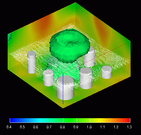
This image shows three types of data. The first is the density which is colored using the colors in the legend at the bottom of the image and is visualized using three 2D slicing planes (the "walls") and an isosurface (the "mushroom"). The second is the momentum which is represented by the white arrows (this are much clearer in the full size image). The final is are the embedded boundaries which are represented by white polygons.

Full size GIF image (256K)
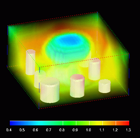
This image shows the density using volume rendering with the colors in the legend and varying opacities. The embedded boundaries are also shown as solid white polygons.

MPEG Movie (1.8 Mbytes)
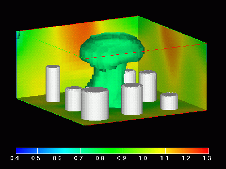
This image shows a frame from an MPEG movie (1.8 Mbytes) in which density isosurfaces are animated using density values in the range 0.4 to 1.3 (see legend).

MPEG Movie (1.8 Mbytes)
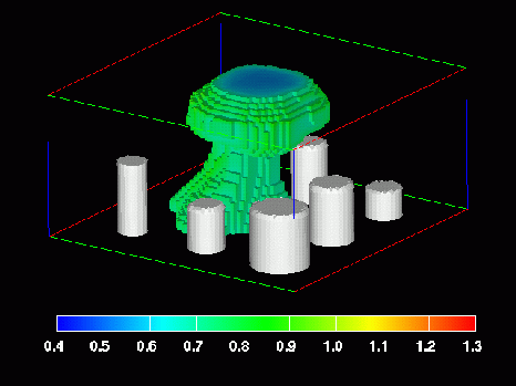
This image shows a frame from an MPEG movie (1.8 Mbytes) where the flattened ANAG AMR data is represented using AVS unstructured cell data (UCD). Here the density is view, a threshold is set, and all cells with values less than this threshold are shown (see legend for colors). This threshold ranges from 0.4 to 1.3 in the movie.
Conclusions
There were several problems with all the above approaches to using AVS to visualize the ANAG AMR data. First, all the data was flattened to one grid so that there was no visualization of the ANAG AMR data in it's native form. To go beyond this using AVS fields, it would be necessary to add a user defined data type that contained some form of collections of fields and then extend the necessary AVS modules to visualize these or construct some type of iteration capability. Without source code for the AVS modules this would entail writing from scratch any AVS module which dealt with fields that we wanted to use.
The AVS UCD data type allows some oppurtunity to represent the ANAG AMR data directly but it still isn't hierarchical in nature, the modules can't do much with cell centered data (see below), and storage requirements go up by a of factor 4-8 compared to the storage necessary for the raw data.
Second, all the field modules and almost all the UCD modules require the data to be converted from cell centered to vertex centered. This might not be a problem to visualizations that are "just for show" but the researchers need the ability to view and peruse their data in an unmodified form. To do this (i.e. cell centered visualization) would require rewriting AVS modules for which we don't have the source code.
Finally, the lack of source code for AVS modules (which was mentioned in all the previous problems) makes extending it difficult at best and it definitely needs to be extended in this case. For this reason we will be looking into using other visualization tools/systems which have more open source access (e.g. Vtk).